Network Diagrams for Diagnosis and Troubleshooting Lucidchart Blog
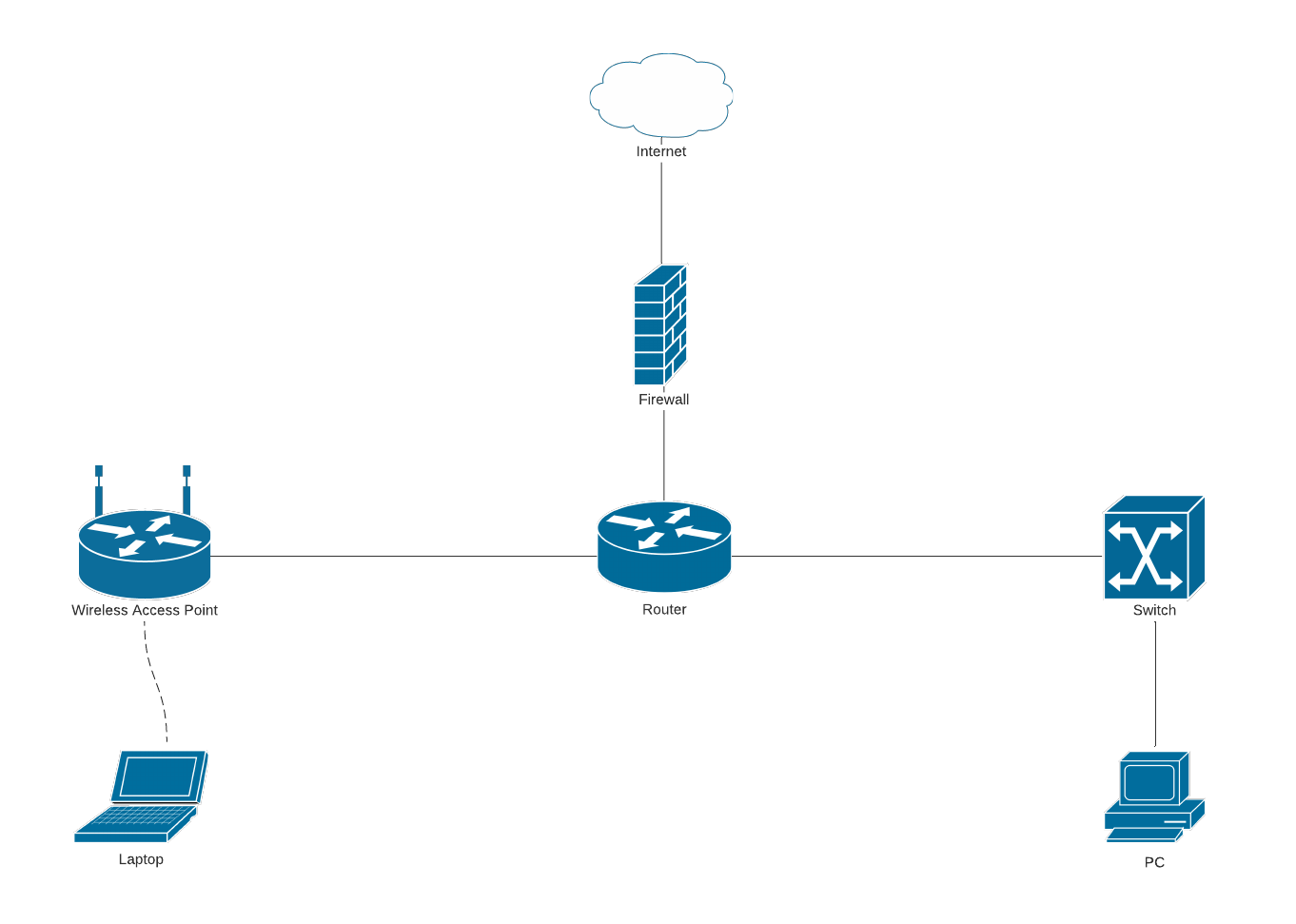
1. Symbols - the LND uses symbols that will represent the types of equipment included in the network. Below are the usual symbols used to present the usual instruments such as the bridge, printer, firewall, router, etc., in a simple logical network diagram. 2. Events - The events in the LND always appear in circles.
Free Editable Logical Network Diagram Examples EdrawMax Online
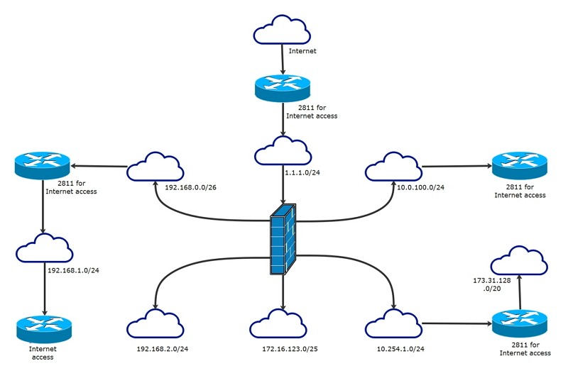
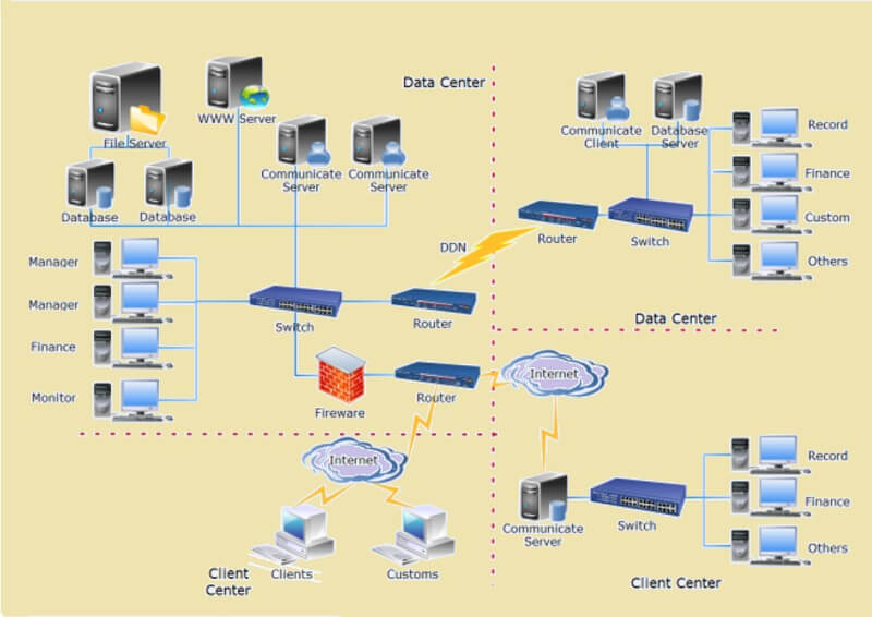
A logical network diagram refers to the data flow throughout a network. Some elements that are illustrated in a logical network diagram include subnets, routers and firewalls, traffic flow, and routing domains. Logical network diagrams are used by IT professionals to better understand how data is transmitted throughout their network.

Logical And Physical Network Diagram
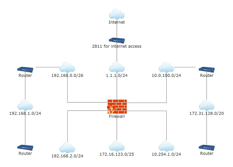
A logical network diagram illustrates the flow of information through a network and shows how devices communicate with each other. It typically includes elements like subnets, network objects and devices, routing protocols and domains, voice gateways, traffic flow and network segments.
Free Editable Logical Network Diagram Examples EdrawMax Online
A logical network is a software-defined network topology or routing that is often different than the physical network. It appears to the user as a single, separate entity, although it might, in fact, be either an entity created from multiple networks or just a part of a larger network. Logical network is a broad term that can be used for many.
Logical Network Diagram Template MyDraw
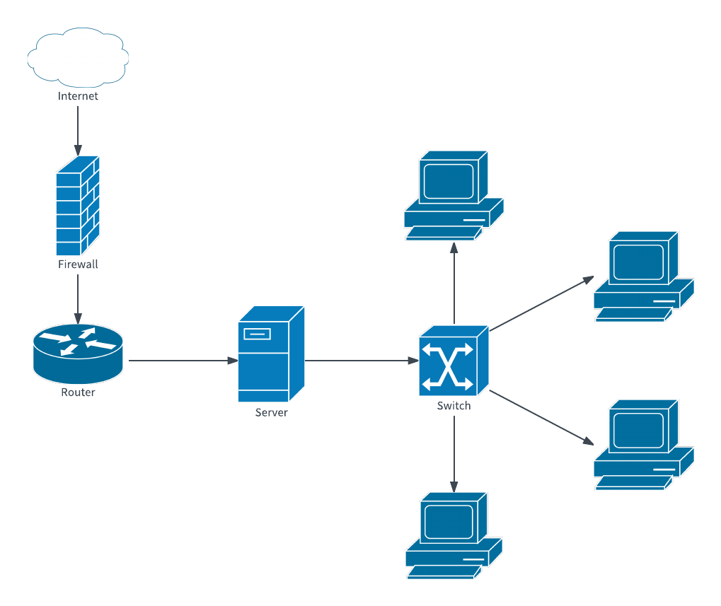
Logical network diagram template Server network diagram template Simple network diagram template If you just need a high-level overview of your network, start with this simple network diagram template. Our network diagram software includes a vast library of related shapes, so you can expand your network diagram as needed.

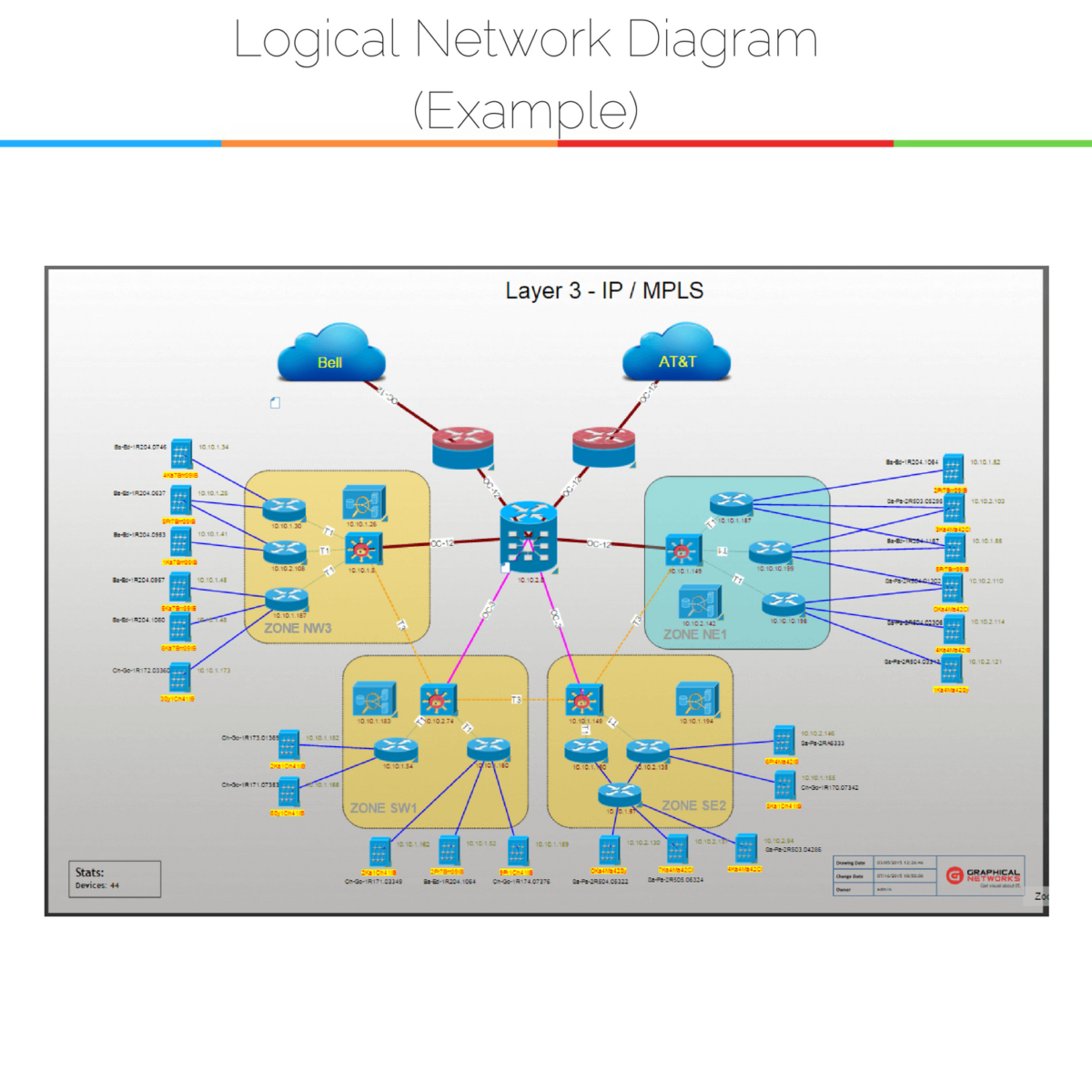
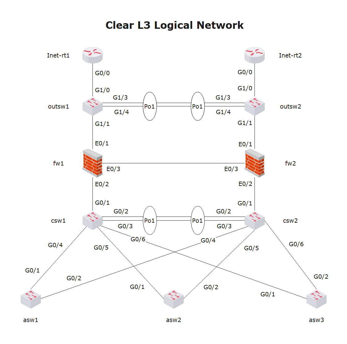
How to Draw Clear L3 Logical Network Diagrams Packet Pushers
Logical (or overlay): This shows how data flows within a network and from one device to another, regardless of the physical connections among devices. While the logical network uses the physical connections for data transfer, the actual flow of data is defined by the logic not the physical connections. How do I diagram a network topology?
Come to Know the Logical Network Diagram and Its Examples
Connectors in a logical diagram connect a device to a subnet and represent a layer-3 (or sometimes layer-2) presence on the subnet. There is no need in this diagram for different colored connectors, so always use a solid black pattern.

Simple Logical Network Diagram Examples Visio
In the diagram, the logical components of a network refer to the information that travels from source to destination. TheUser information includes the data transported in a framework via the network. Frames have three parts: The header The data The trailer Frames have destination addresses using which data is traveled to its intended destination.
What is a Logical Network Diagram? DCIM, Network Documentation, OSP Software
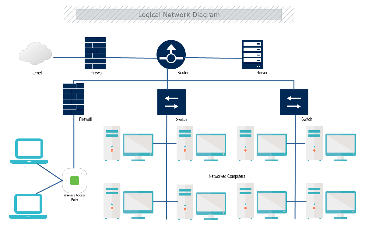
Logical network diagrams This type of diagram shows how information flows and devices communicate with each other in a network. In addition to traffic flows and devices, it usually includes subnets, routing protocols and domains, network segments, and voice getaways. Additional network diagrams
Logical Network Diagram Template Lucidchart
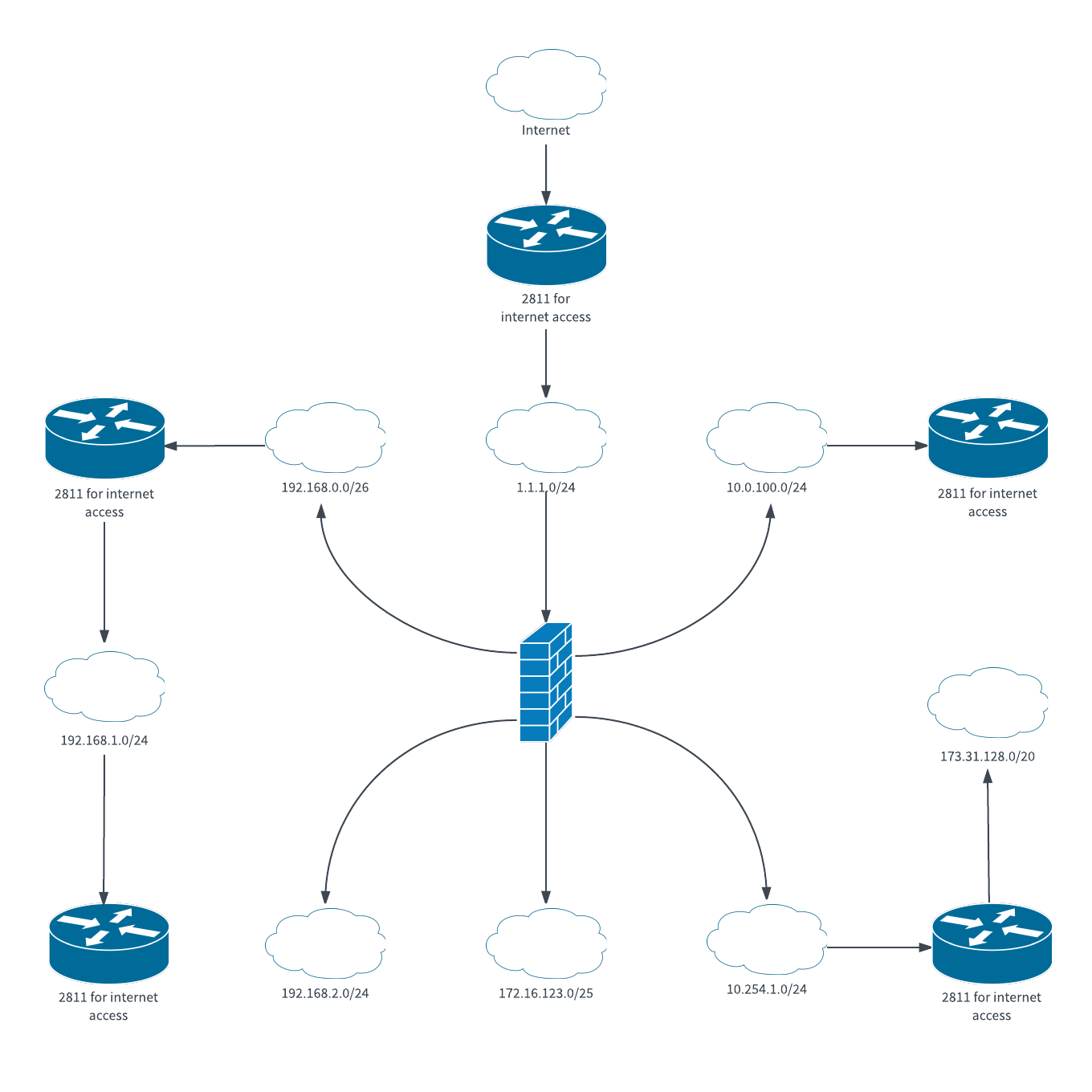
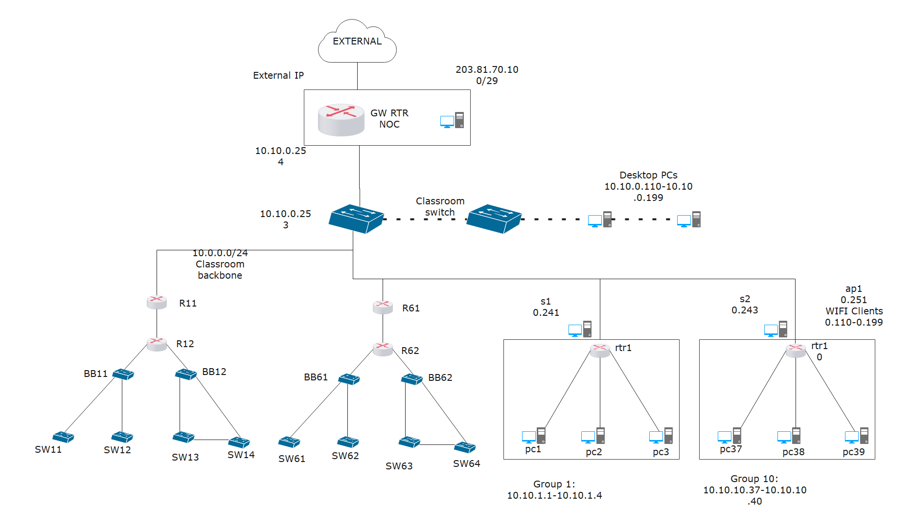
A logical network diagram depicts how information in the network flows. In a logical diagram, you'll generally visualize the following elements in your logical network topology: subnets (such as: IP addresses, VLAN IDs, and subnet masks,) network objects (routers and firewalls) specific routing protocols routing domains voice gateways traffic flow
What is Logical Network ?
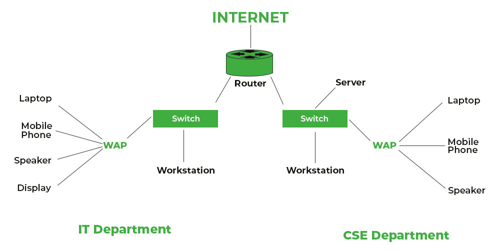
A logical network diagram shows the relationship between the components in a network. In other words, it shows the dependencies between the different components. In a network diagram, nodes are connected with the help of connectors. There should be one endpoint per layer and no loops. This way, viewers can easily understand the relationship between […]
Network Diagram Templates and Examples Lucidchart Blog
A logical network diagram shows how data and information flow in a network. In a logical network diagram, you can see elements such as routing domains, network objects (firewalls and routers), subnets (VLAND IDs, IP addresses, subnet mask), voice gateways, and specific routing protocols, network segments, and traffic flow.
Logical Network Diagram Complete Guide EdrawMax
Logical network diagrams are useful for engineers, they can be used in different ways to manage networks more effectively: Troubleshooting network problems: Logical network diagram can help you quickly rule out an issue caused by a firewall if service is out between two IP addresses;
Cisco Network Examples and Templates
Logical Network Diagrams visualize the computer and telecommunication networks logical structure. They are used by IT professionals and corporate IT departments, network and system administrators to visually document the topology of computer and telecommunication networks.
Logical Network Diagram Complete Guide EdrawMax
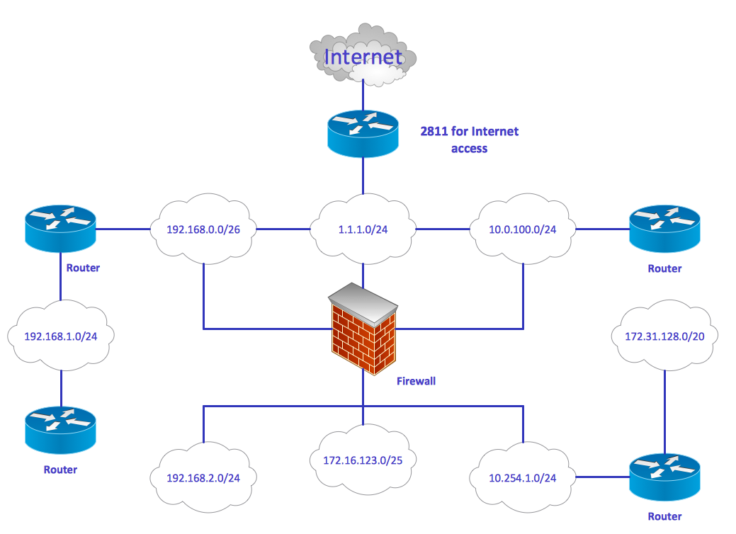
A logical network diagram describes the way information flows through a network. Therefore, logical network diagrams typically show subnets (including VLAN IDs, masks, and addresses), network devices like routers and firewalls, and routing protocols.

The Proposed Logical Network Diagram for the CDN Download Scientific Diagram
Network diagrams are the schematic representations of the underlying physical or logical network topologies. These diagrams consist of nodes and lines, with different icons to make it easy to quickly see different elements on the network.